Seismometry Adventure
Last Updated 12/28/01
Here is the story of a fun project in which we set out to build an amateur seismometry
station and record the signals from distant earthquakes. Much useful related
information can be obtained from the website of the
Pacific Seismic Network (PSN).
The the complete project will include the following elements:
-
-
-
-
Installation of station at a suitable site
Adventures in detecting or attempting to detect earthquakes
The Seismometer
The seismometer design
is based on one by Pete Rowe, WA6WOA who was kind enough to
share many details of his efforts with me. It consists of a pendulum that is substantially
horizontal, such that the natural frequency of oscillation is on the order of 15
seconds or so. A coil of many turns of wire is mounted on the bob of the pendulum
and is coupled to a strong magnet such that relative motion between the coil and
the magnet create a voltage across the coil. The magnet is fixed to the frame of
the seismometer and thus shakes as the earth moves. The coil on the other hand is
very weakly coupled to the frame (as is evidenced by the long natural period of oscillation).
Thus the coil largely stays still (in the axis along which it is free to move) while
the coil shakes. It is the relative motion (velocity) between the magnet and coil
that leads to a voltage signal at the terminals of the moving coil.
|
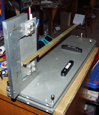
Here is a picture of the horizontal
pendulum in development
showing
the supporting hinge in the foreground,
the golden colored boom,
and a lead weight for a bob.
|
The supporting hinge is special. It is a clever flexure-based hinge which uses
some fine music wire to make a substantially frictionless hinge. The photo below
shows the arrangement.


Detail
of Hinge Flexure
|
The geometry of the hinge is such
that the two wires are both
in tension
the pendulum bob tries to rotate
the hinge under gravity. The wire
is
stiff enough, however, to support the load
vertically, but can bend with
a predictable
spring constant as the bob swings on the
hinge. The spring constant
is not a
negligible factor in determining the
period of oscillation....More
about that
later.
|
The equation for the voltage developed by the moving magnet in the coil is given
by:
V = v (dB/dx)*N*A where:
V = voltage across the coil, v is relative
velocity of coil and magnet,
dB/dx is the gradient of the magnetic field, N
is the number of turns in
the coil, and A is the average area of a turn in the
coil
The astute reader will recognize some approximations and simplifications
in this expression, but the spirit of the interaction is mostly represented.
Some
characteristics that lead to a good signal-to-noise ratio for the seismometer include:
Long
period of oscillation, large number of turns of wire in the coil, a strong magnetic
field gradient in the direction that the coil is free to move. The area of the coil
should be big enough to catch all the available flux from the magnet, but not so
big as to become a large antenna for noise pickup.
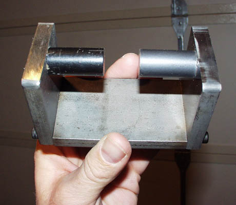
My magnet
The photo below shows my magnet. It
is made out of some steel bar that has been cut and ground into pieces that bolt
together to form a C-shaped flux return structure. To this are attached two very
strong Neodymium-Iron-Boron permanent magnets that have diameters of about 3/4 inch
and length about 1.25 inch.
|
The steel bar is 3/8 inch thick
and 2 inches wide. The short
ends of the C structure are about
2 3/8 inches long, the back of the
C is 3 1/4 inches long so that the
gap in the magnet is 3/4 inch.
|
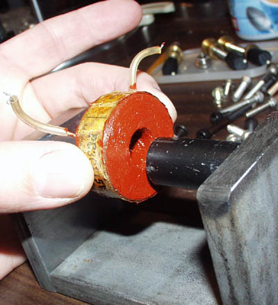
The coil that I am using is shown below. I pressed it out of an old relay that
had a 115 volt coil with a nice geometry. I have yet to determine the number of turns,
but I plan to do that. I painted the coil with Corona Dope, a high voltage insulating
enamel to stabilize the fuzzy insulation on the surface of the coil and to improve
the electrical insulation.
|
Here you can see how the coil
size compares
to the magnet
pole size and gap.
|
Seismometry
Amplifier/Filter
The voltage output from the coil is connected to an amplifier/filter
circuit. The purpose of this circuit is to provide a voltage gain within the
bandwidth of about .05 to 10 Hz and very little gain outside that bandwidth.
This improves the signal-to-noise ratio in that the interesting earthquake
related signals are expected to lie within this bandwidth, and extraneous noise
of higher and lower frequencies will be ignored. The circuit I am using is based
on and very similar to that available
for sale by Larry Cochrane.
The output of the amplifier/filter circuit is connected to the input of the
Analog-to-Digital converter (ADC) card in the data acquisition computer.
Data acquisition computer and ADC sub-system
The computer that we are using is an old cast-off 486
system running an old version of Windows 3.1 or DOS depending on my mood. A
Pentium would be nice, but it really doesn't matter for the data logger. The
data acquisition card is a PcLabCard PC-711s which happens to be supported by
the EMON program which is available for free off the web. I had a couple of
these ADC cards in my junk pile from previous projects, so that set the choice of
ADC and logging program. If I hadn't had those, I probably would have purchased
and ADC card from Larry Cochrane and used his SDR program. My ADC card permits
up to 16 inputs which can be digitized to 12 bit resolution (one part in 4096).
This is plenty good to see earthquake signals. Lots of guys have done it with
only 8 bit resolution.
Seismic data logging computer program
As I mentioned above, I am using EMON because
it supports my ADC cards (thus saving a couple hundred dollars on the project).
It can be downloaded from the software section of
this PSN page.
Current Project Status as of 12/28/01:
The computer runs and I can wave the magnet in the coil and
see wiggles going into the data logging program. This is with the coil connected
directly to the input of the ADC card. I can log data and recall it from disk
files using the various utility programs that I downloaded from the sites
indicated above. The magnet is now mounted on the seismometer, and the boom is
equipped with a paddle to hold the coil. I have mounted the whole pendulum
assembly on a separate plate which has leveling screws for adjustment, and
springs to keep the whole thing together.
Next I need to finish the mounting of the coil
and its wiring, and I plan to attach some adjustable boom stops to facilitate
transporting the seismometer. Then I need to finish mounting the whole thing in
the windproof box, and finish the power supplies and amplifier electronics. At
that point I will be ready to see how noisy my neighborhood is.
 |
The photo at the
left shows the current status of the seismometer as of 12/28/01 |
This project is a work in progress...please check in from time to time to see
the developments.